PERCE's important product - non-metallic follow-up head 100, the laser beam enters the inner cavity of the cutting head through the reflector, and through the focusing lens, the energy of the laser beam is concentrated on a certain point, and the surrounding materials are melted at high temperature to form processing marks to achieve the cutting effect. The non-metallic follow-up head moves the focusing lens according to the undulations of the material surface, changes the position of the focus, and keeps the focus position at a certain distance from the board surface, so as to accurately cut the material. It can process a variety of materials, such as acrylic, density board, wood board, cloth, etc.

Component Description

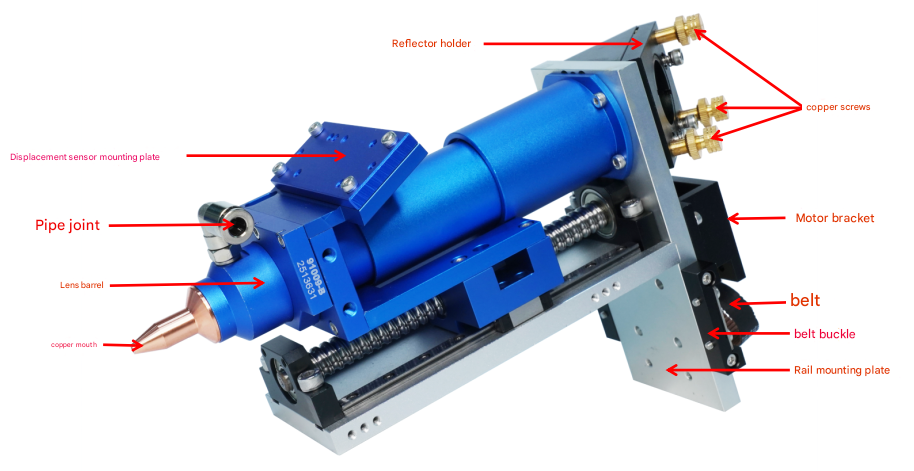
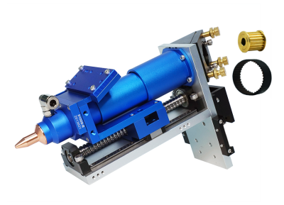
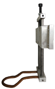
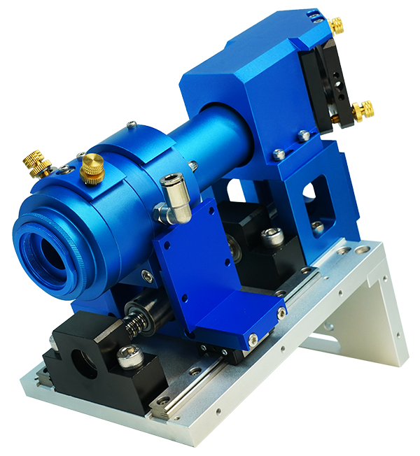
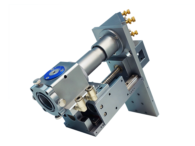
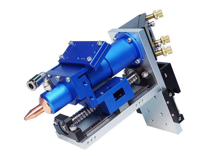
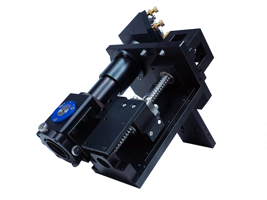
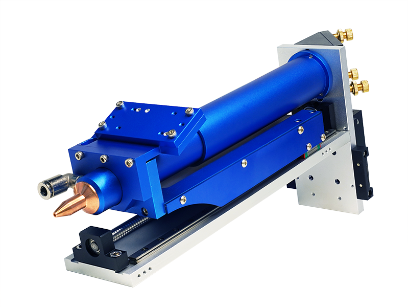
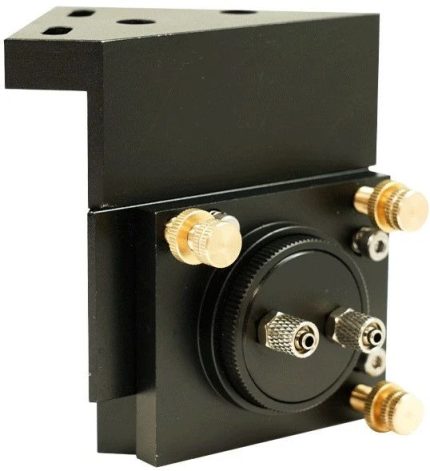
Rail mounting plate:Fixed body
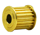
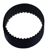
Belt buckle:belt installation
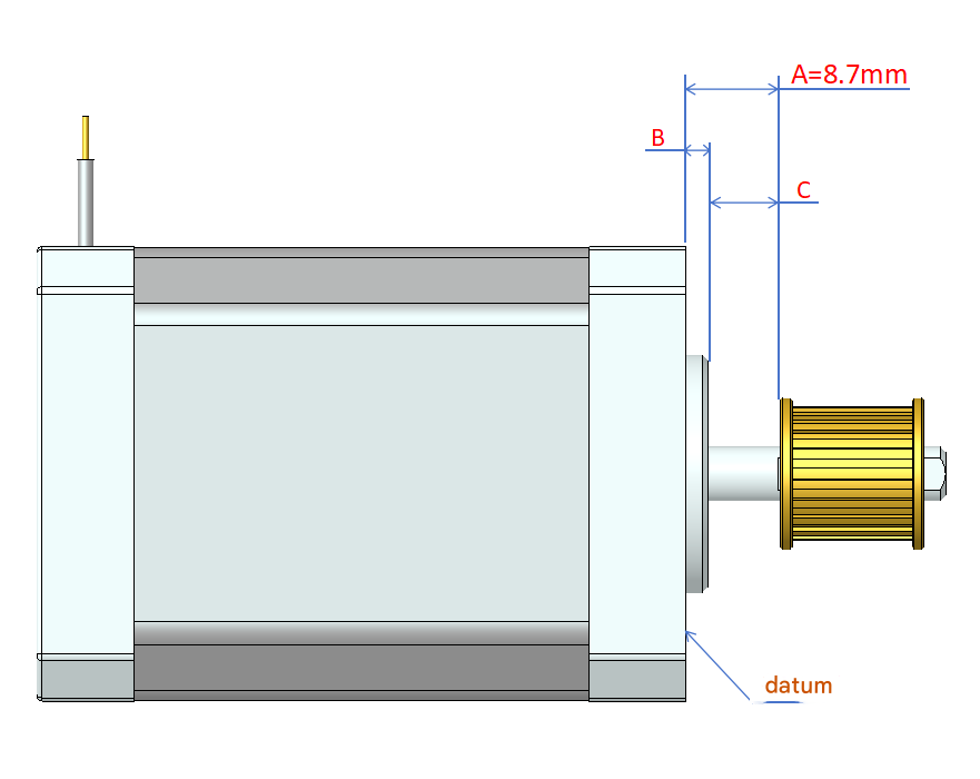
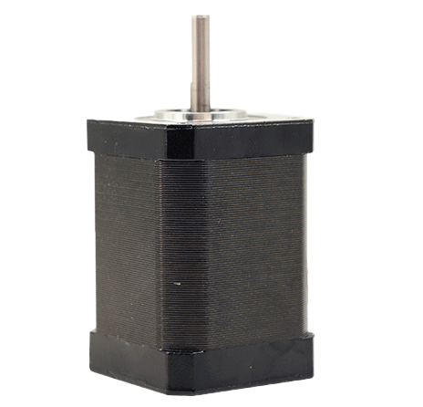
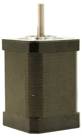
Motor bracket:Mounting the Motor
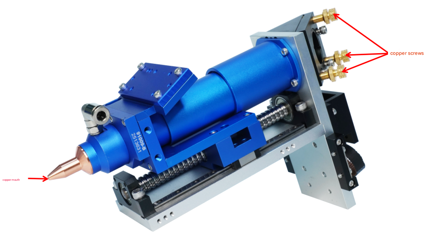
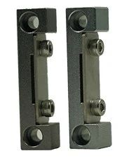
Copper screws:Light adjustment
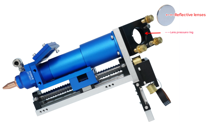
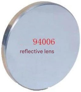
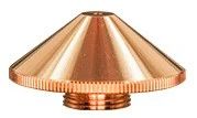
Reflector frame:Installing the reflector
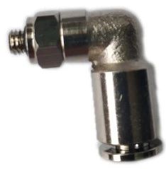
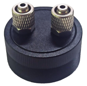
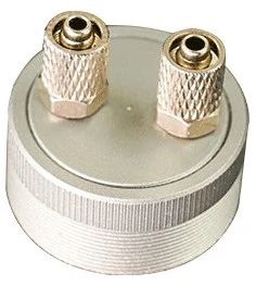
Pipe Fittings:Blowing air to cool the material
Displacement sensor mounting plate:Installing the displacement sensor
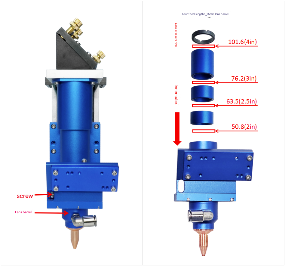
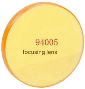
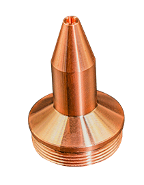
Lens tube:Install the focusing lens
Installation Dimensions

Instructions for use and debugging
1.Lens installation
(1)Reflective lens installation
Use tools to remove the lens pressing ring of the reflector frame, put the reflector lens into the lens hole (mirror surface facing inward, back side facing outward), press it flat, and after ensuring it is flush, lock the lens pressing ring.

(2)Focusing lens installation
First loosen the screws and take out the lens barrel (there are lens pressing ring and inner lens barrel in the lens barrel), use the tool to rotate and take out the lens pressing ring, and then take out the inner lens barrel. You can choose different focal lengths according to your needs, supporting 50.8/63.5/76.2/101.6mm focal lengths, put the focusing lens into the lens hole, flatten it, ensure it is flush, and then lock the lens pressing ring to complete the lens installation.

2.Light adjustment
The light is adjusted by fine-tuning the copper screw. If the light beam passes through the nozzle correctly, the light adjustment is correct.

3.Maintenance
(1) Regularly maintain the Z-axis transmission system to ensure it is clean and lubricated.
(2) Regularly check the lens in the laser head to ensure it is clean.
(3) Regularly check the nozzle. If there is any damage, please replace it in time.
Motor Installation Instructions
Dimensions of the synchronous wheel pressed into the motor shaft:
- Reference surface to synchronous wheel A=8.7mm
- Please measure the motor size B
Therefore, C=A-B
Control the distance C when pressing the synchronous wheel to ensure the synchronous belt is level

Precautions
- Non-professionals are not allowed to disassemble.
- You need to install the upper and lower limit switches of the Z axis by yourself. After installation, make sure that the upper and lower limit switches of the Z axis work normally and effectively before turning on the machine.
- After the laser equipment is turned on, invisible light will be generated, and professional personnel are required to operate it. Please pay attention to safety.
- It is required to connect clean and dry compressed gas. (For example, use a pneumatic triplex to filter, reduce pressure and refuel the gas to ensure the normal operation of the pneumatic actuator and prevent malfunctions due to impurities, excessive air pressure or lack of oil.)
Order Model
Product Parameters
Order Model | PERCE91009-B |
Reflector diameter/mm | 30 |
Focusing lens diameter/mm | 25 |
Supported focal length/mm | 50.8/63.5/76.2/101.6 |
Stroke/mm | 88 |
Overall dimensions/mm | W85*H217*D160 |
Weight kg | 1.2 |
Product Information

Non-metallic follower head 100
Product accessories

94005 Focusing lens

94006 Reflective lens

94011 Quick Connector

94009-B Water Cooling Assembly

94007Motor

94013Synchronous wheel

94008Drive

94014Timing belt

94017Sensing components

94016Long copper mouth

94027Belt Buckles
Reviews
There are no reviews yet.