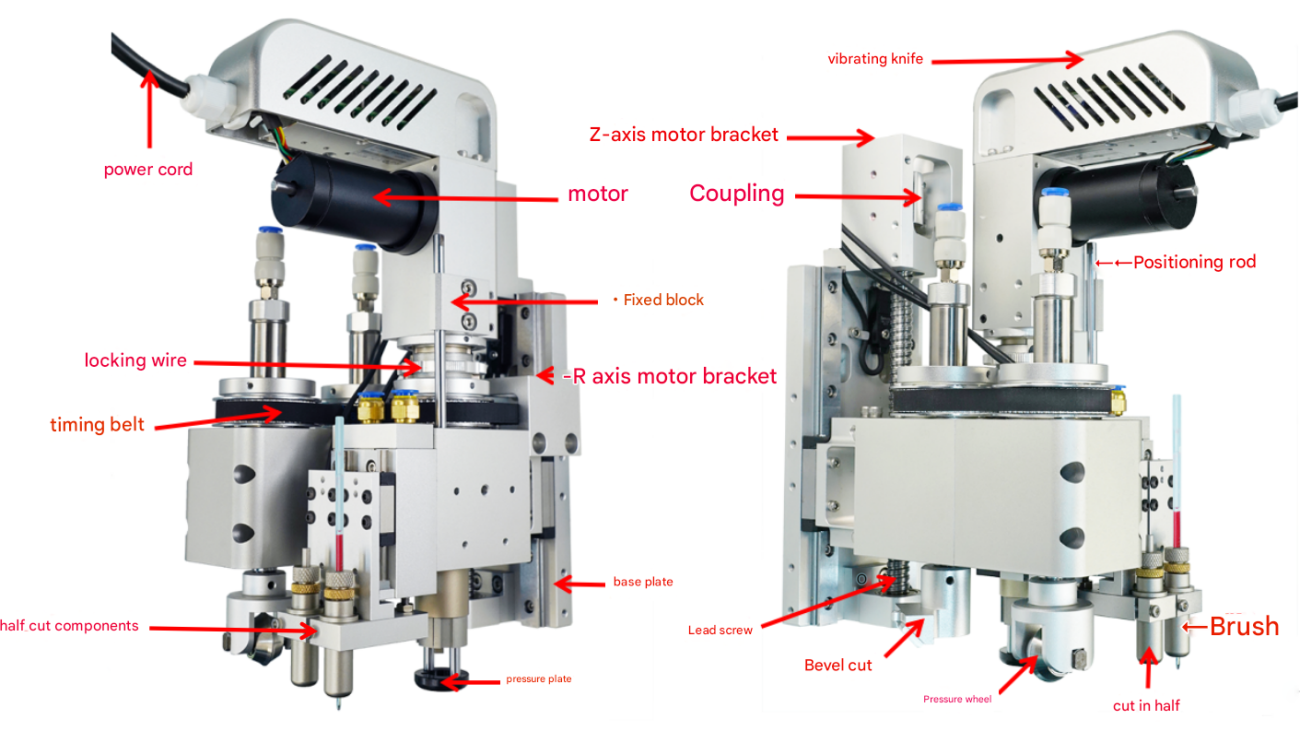
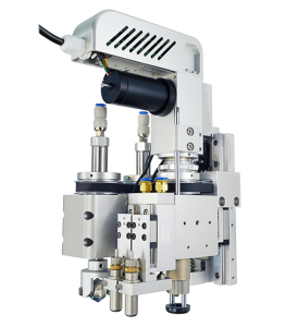
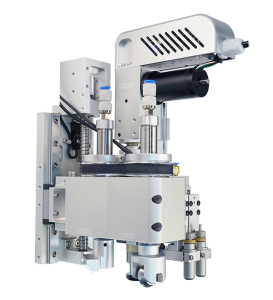
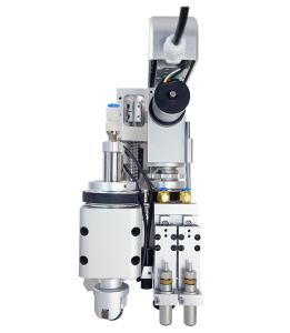
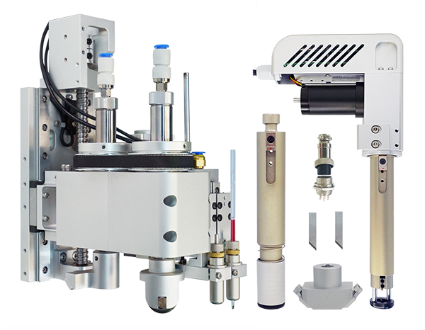
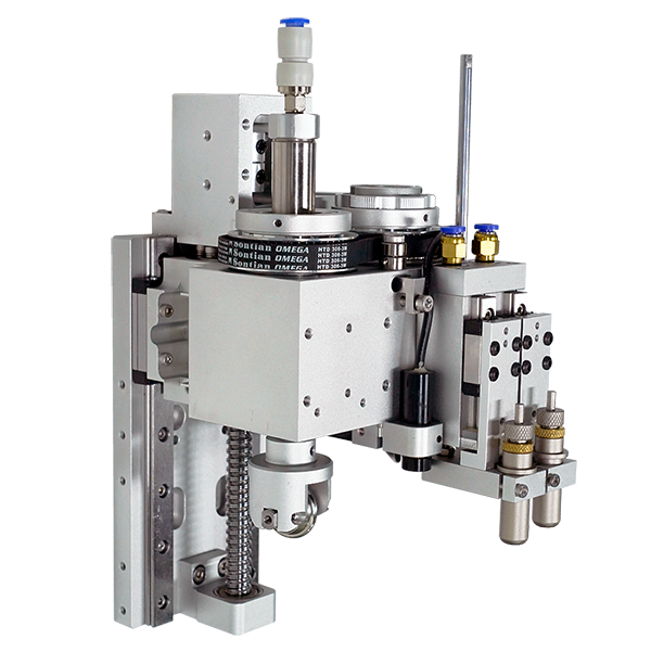
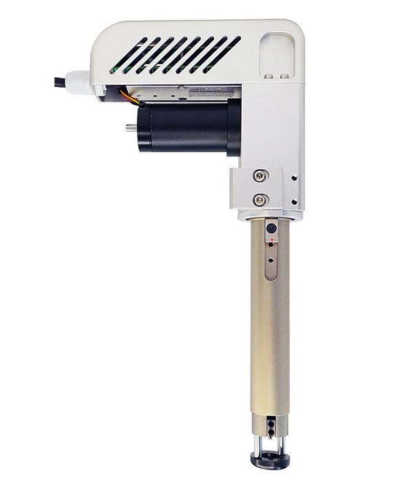
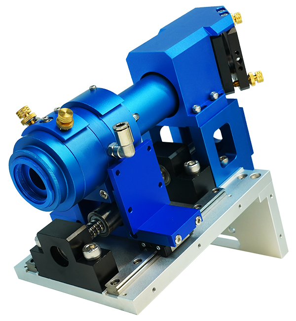
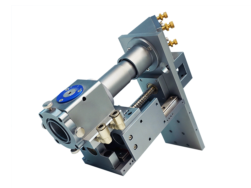
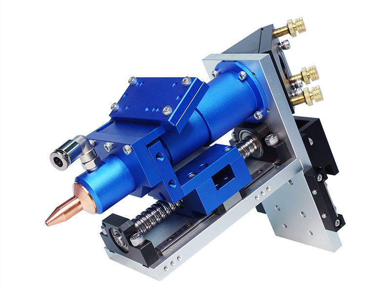
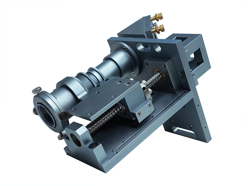
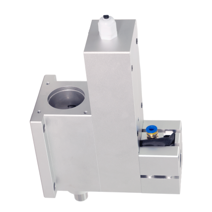
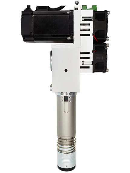
The combined cutter head integrates the functions of vibration cutter, pressure wheel, bevel cutter, brush and half-cut, which can meet the needs of various processes on the cutting machine and improve the processing efficiency.
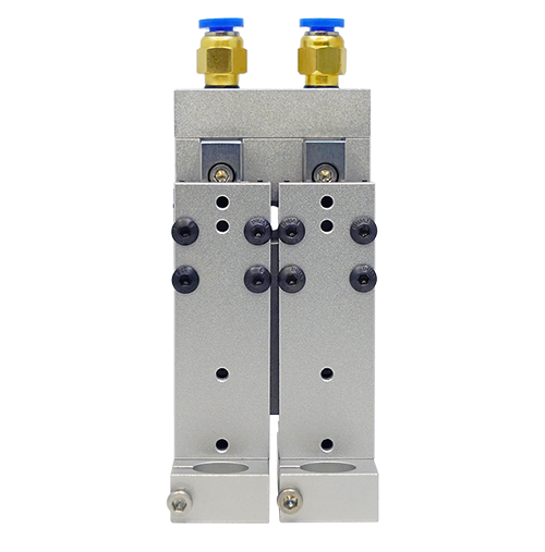
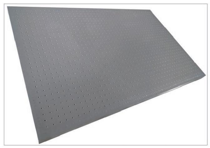
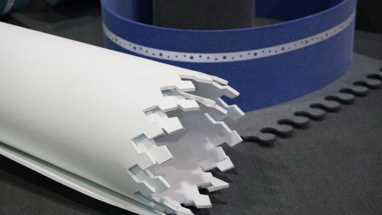
The vibration cutter pressure plate is controlled by the cylinder. The cylinder rod extends out and the pressure plate presses the work surface tightly. The cylinder rod contracts and the pressure plate rises. It can process advertising KT board, foam board, ABS plastic, corrugated plastic board, corrugated paper, cardboard, gray cardboard, sealing ring, PP paper, PP adhesive, car sticker, ABS plastic, thin plastic, rubber cloth, imitation leather, snowflake paper, soft glass, reflective sticker and other materials.
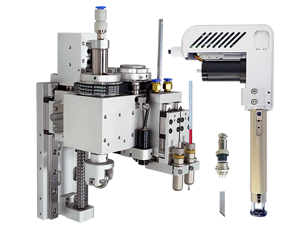
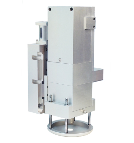
Component Description
Component Description
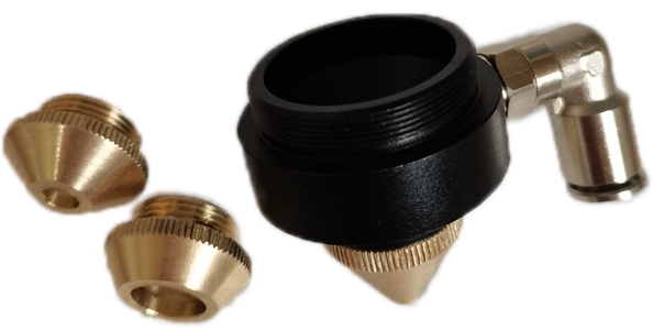
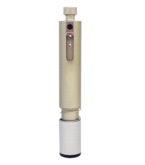
Combination cutter head body: can be installed with vibration cutter, drag cutter, built-in pressure wheel, optional bevel cutting;
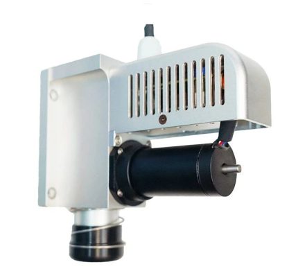
Vibration cutter: the motor drives the blade to reciprocate at ultra-high speed to cut the material;
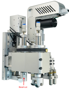
Bevel cutting: processing V-shaped grooves and bevels, optional single bevel cutting and double bevel cutting;
Pressing wheel: the round wheel rolls over the material to produce an indentation effect;
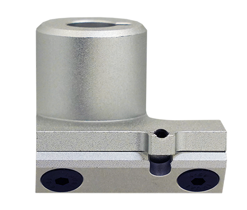
Positioning rod: used to clamp the tool ear to prevent the upper part of the tool from rotating with the knife barrel;
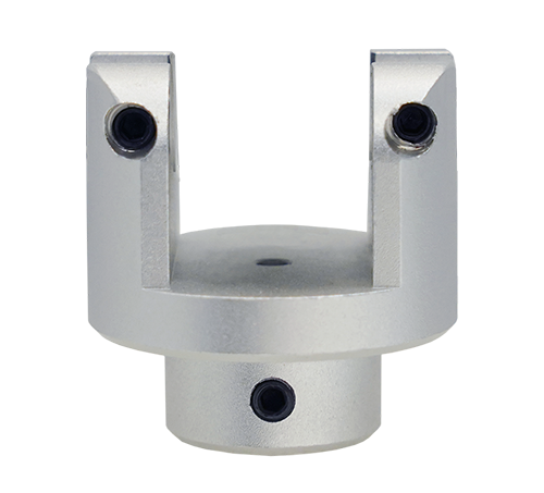
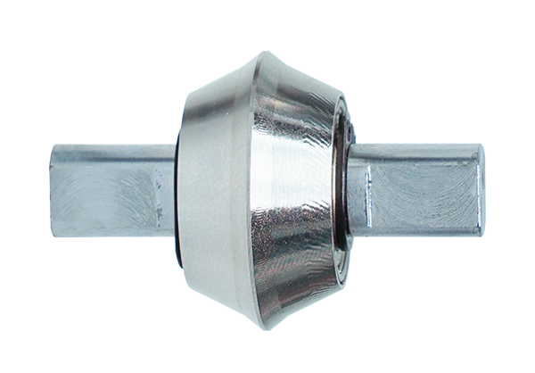
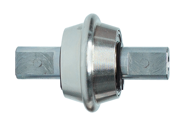
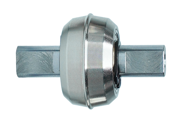
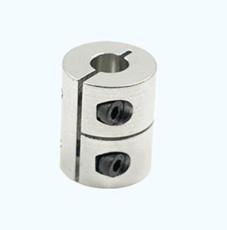
Coupling: used to connect the Z-axis motor and the lead screw;
Locking wire: fix the tool (vibration cutter or drag cutter);
Base plate: used to fix the combination cutter head body;
R-axis motor bracket: control the installation position of the tool rotation motor;
Z-axis motor bracket: control the installation position of the tool lifting motor;
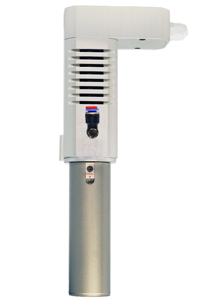
Power cord: provide power for the vibration cutter;
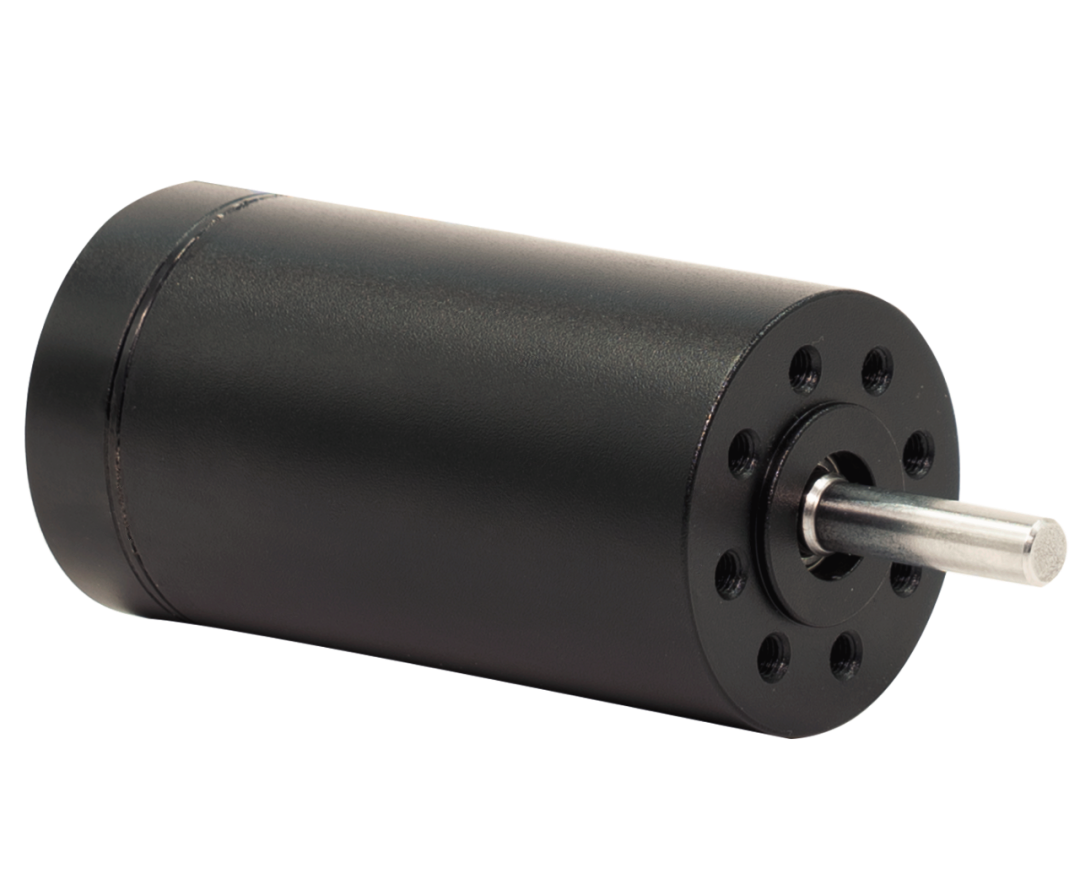
Motor: vibration cutter power element;
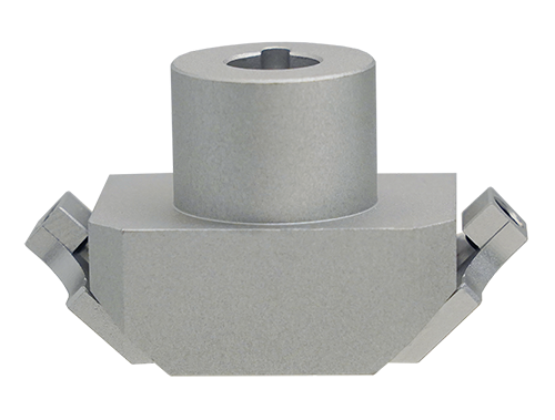
Fixed block: vibration cutter connection support rod.
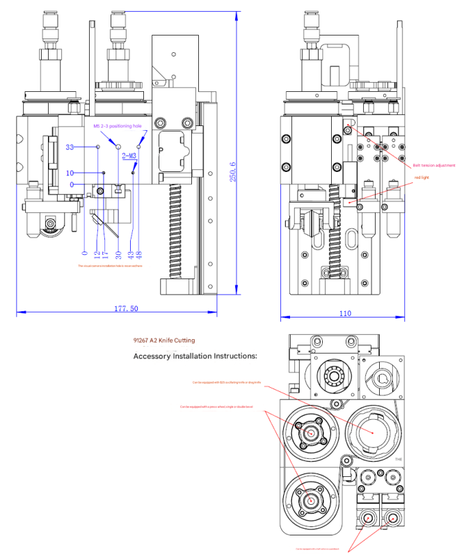
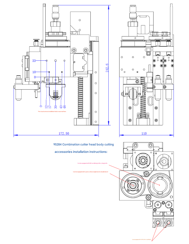
Installation Dimensions
Instructions for use and debugging
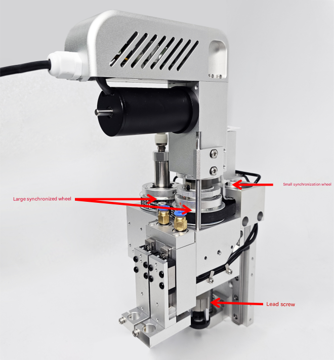
(1) Lead and tooth ratio
The lead of the combined cutter head screw is 4mm, and the tooth ratio is 3:1, i.e. 48 teeth for the large synchronous wheel and 16 teeth for the small synchronous wheel.
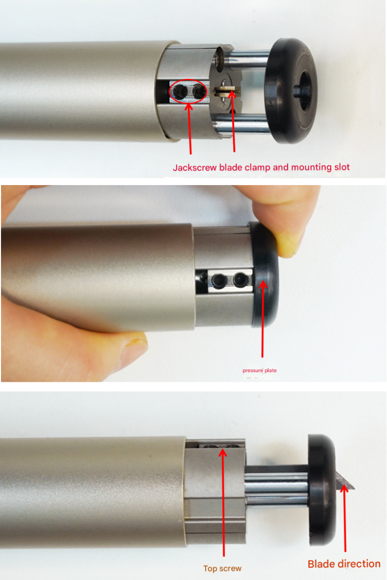
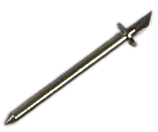
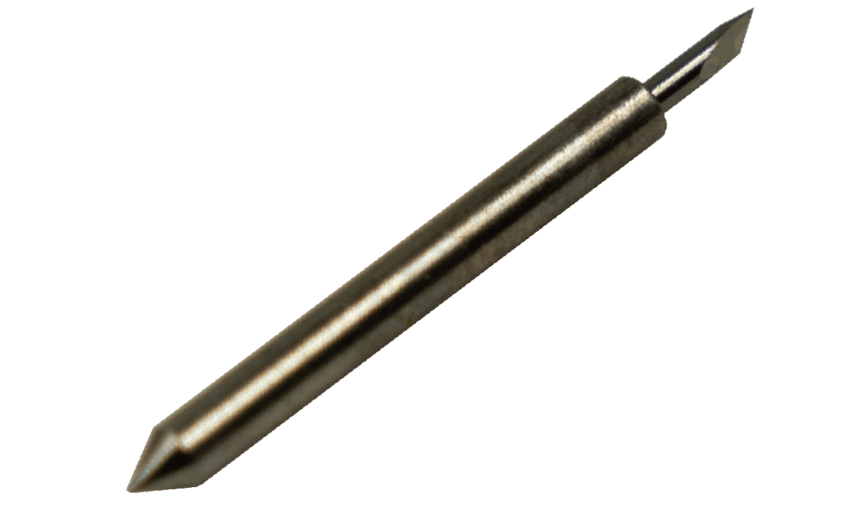
(2)Installation of the vibration knife blade
Loosen the M4 screw, press the pressure plate, insert the blade, and insert the blade until it is inserted to the bottom (the insertion part is about 13mm); tighten the M4 screw, and turn the shaft at the tail of the motor by hand to ensure that the blade can slide easily.
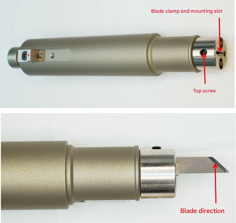
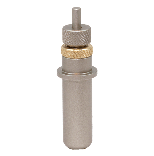
(3)Drag the blade to install
Loosen the M4 top screw, insert the blade into the blade clamp (pay attention to the direction of the blade), and tighten the M4 top screw to complete the blade installation.
(4)Install the cutter head
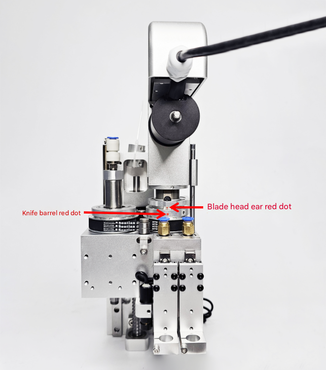
The direction of the blade is consistent with the red dot on the cutter head clamp, and the cutter head is installed on the cutter barrel. When the red dot on the cutter head clamp is in the same direction as the red dot on the cutter barrel, the blade faces forward. When the red dot on the cutter head clamp is in the opposite direction to the red dot on the cutter barrel, the blade faces backward.
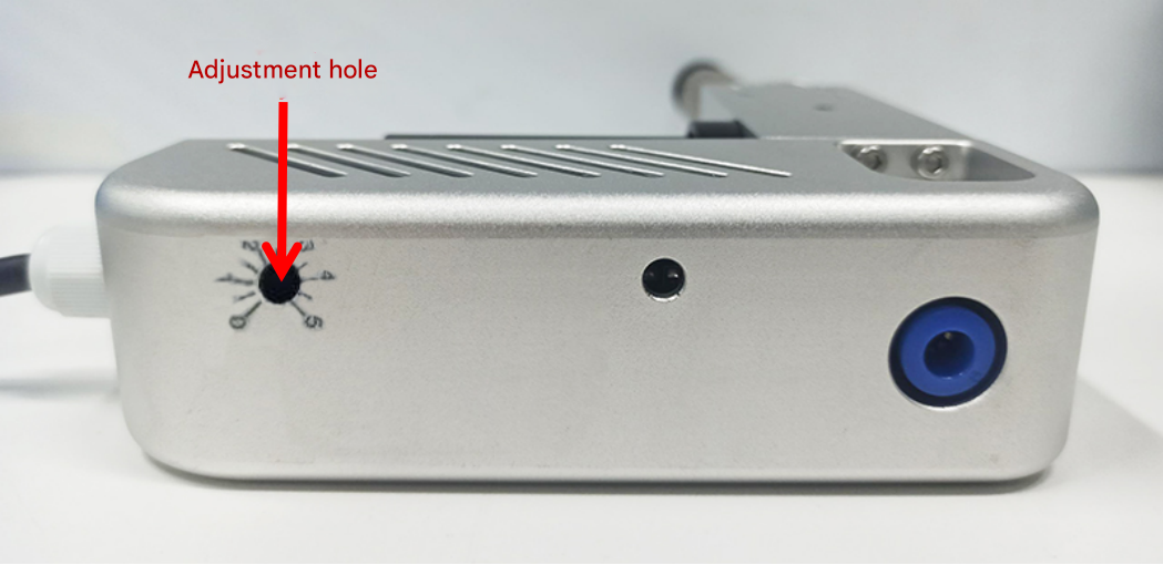
(5)Adjustment of vibration frequency
Insert a small cross screwdriver into the adjustment hole and turn it clockwise or counterclockwise to adjust the vibration frequency. (Note: The adjustment knob is a precision electronic component and should not be adjusted too much).
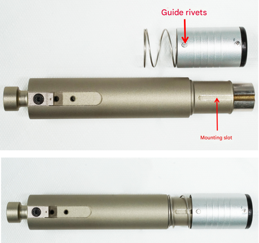
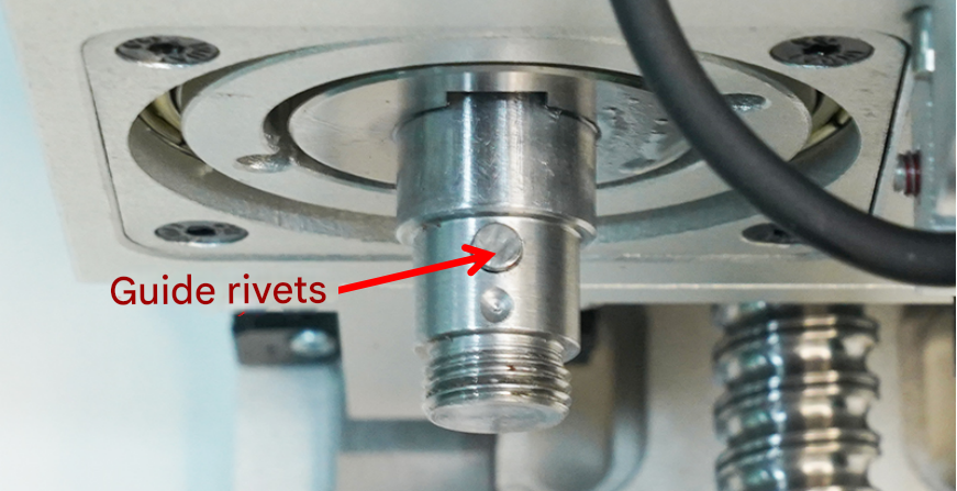
(6)Installation of the drag blade cap
Align the guide rivet on the blade cap with the guide groove of the drag blade handle, and press the blade cap into the handle with a little force. When you hear a click, the blade cap is installed in place. Check whether the blade cap barrel moves up and down smoothly. When pulling out the blade cap, keep the blade cap and the handle in a straight line and pay attention to safety.
(7) Blade clamp removal
Method 1: Use a screwdriver to move the blade clamp back and forth. Once the blade clamp is loose, you can remove it (recommended).
Method 2: First clamp the waste blade with the blade clamp, then clamp the blade clamp with pliers and pull it out.
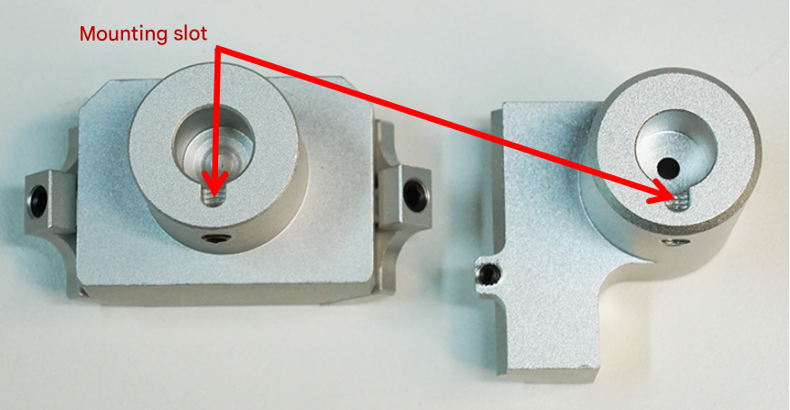
(8)Bevel installation
Align the bevel installation groove with the guide rivet and then tighten the top screw.
(9)Installation of half-cut or brush
Loosen the screws, insert the half-cut or brush, and tighten the screws to complete the installation.
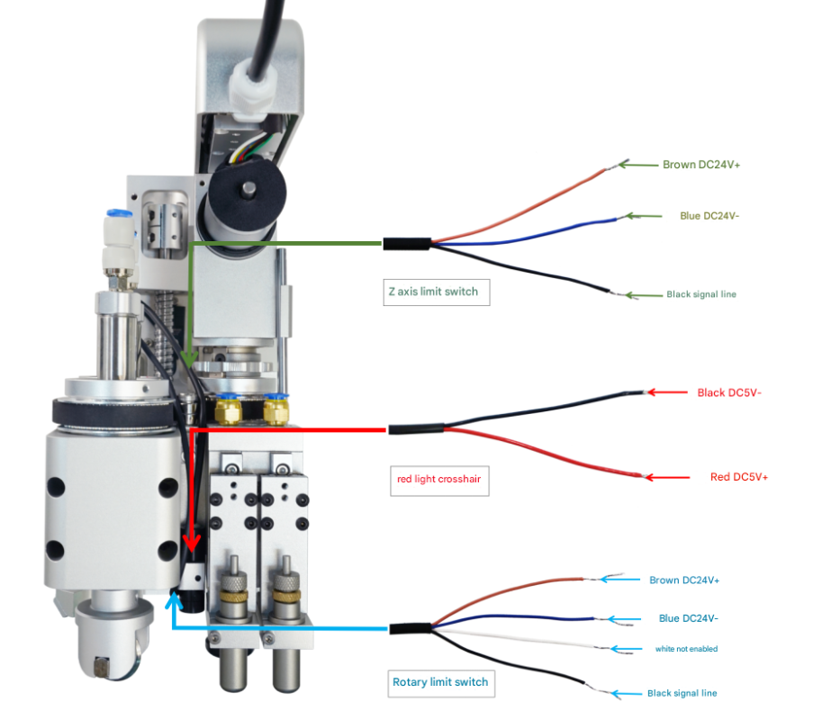
Wiring Instructions
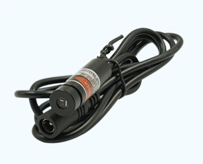
Red right cross hair
Red:DC5V+ Black:DC5V-
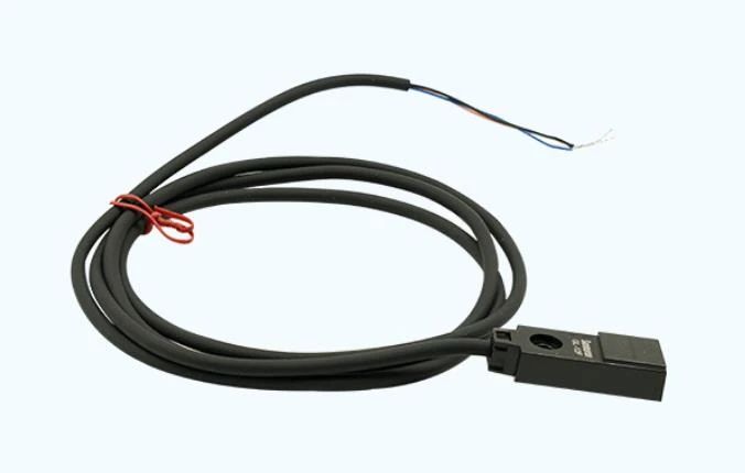
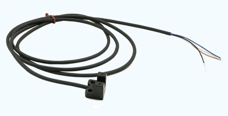
axis limit Switch
Brown:DC24V+ Blue:DC24V- Black:Signal line
Rotary limit switch
Brown:DC24V+ Blue:DC24V- Black:Signal line
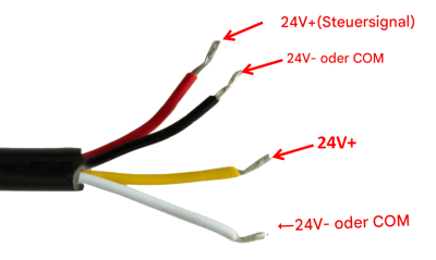
(1)Wiring 1
Red
DC24V+(control Signal line)
Black
DC24V- or COM
Yellow
DC24V+
White
DC24V- or COM
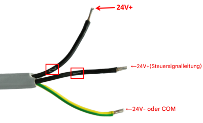
(2)Wiring 2
Black(No.2)
DC24V+
Black(No.1)
DC24V+(control Signal line)
Yellow Green
DC24V- or COM
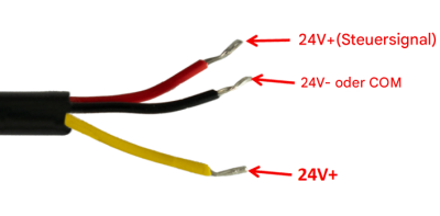
(3)Wiring 3
Red
DC24V+(control Signal line)
Black
DC24V- or COM
Yellow
DC24V+
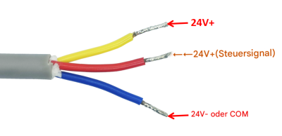
(4)Wiring 4
Yellow
DC24V+
Red
DC24V+(control Signal line)
Blue
DC24V- or COM
Precautions
1. Clean and dry compressed gas must be connected. (For example, a pneumatic triplex is used to filter, reduce pressure and add oil to the gas to ensure the normal operation of the pneumatic actuator and prevent malfunctions due to impurities, excessive air pressure or lack of oil.)
2. The vibration knife is equipped with a separate switching power supply, and it is recommended to be configured with 24V10A or above
3. Before powering on, confirm that the wiring is correct
4. Do not use excessive force when adjusting the frequency of the vibration knife
5. Non-professionals are not allowed to disassemble the blade
6. Pay attention to safety when installing the blade and the blade cap
7. When the motor temperature is too high, it can be cooled by blowing air. The connected cooling gas must be clean and dry
8. Use shielded cables to avoid interference
9. Confirm the tightness of the coupling
Product Parameters
Order Model
Perce 91267
Oscillating knife motor speed RPM
3000-18000
Oscillating knife amplitude mm
1
Oscillating knife motor power/W
100W
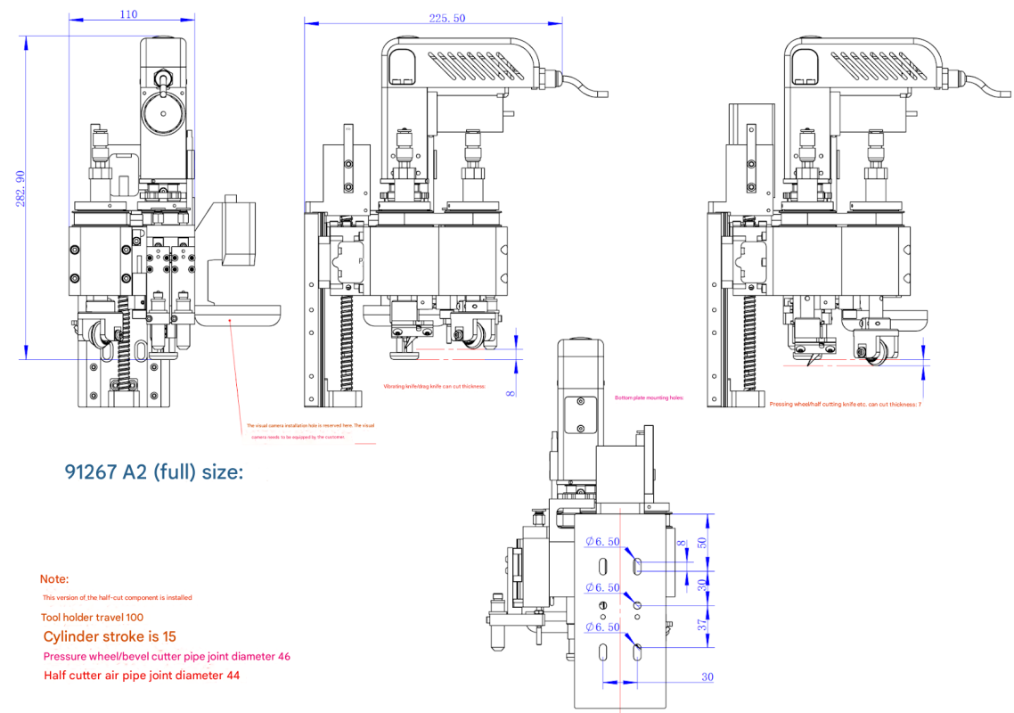
stroke /mm
tool holder:100mm cylinder:15mm
Diameter of air pipe joint Φ
pressing wheel/bevel cutter:6 half cutter:4
overall dimensions/mm
W110/H242.6/D172.5
weight kg
6
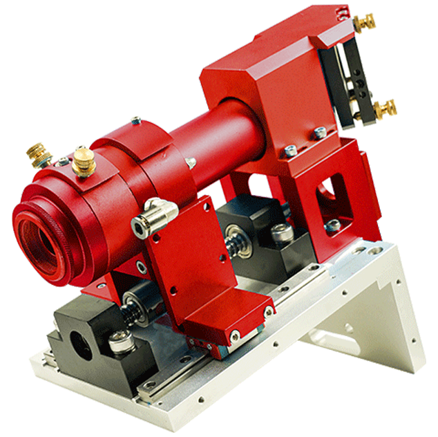
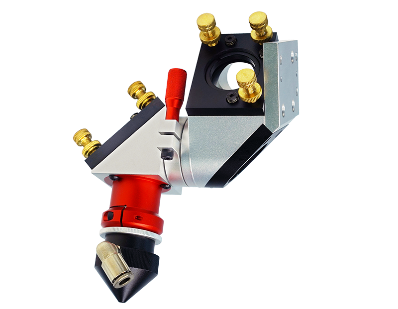
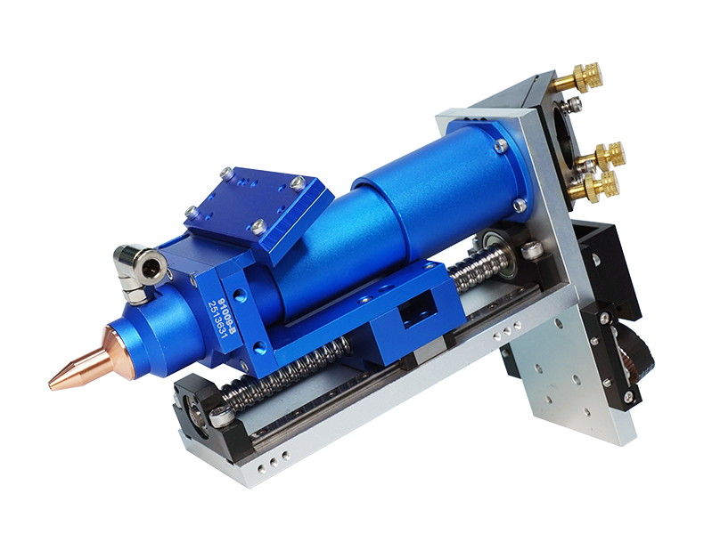
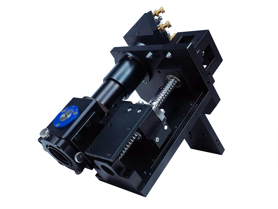
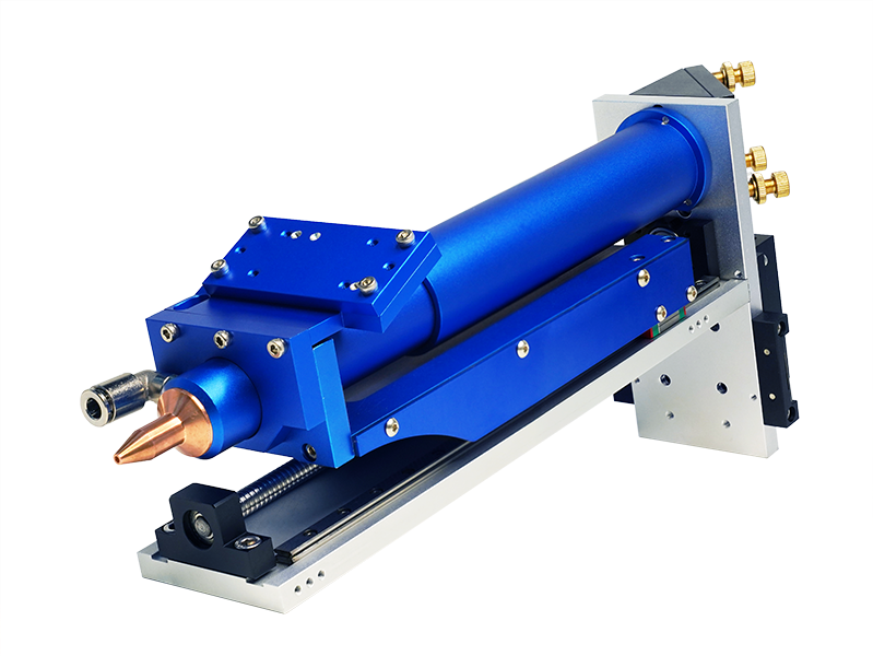
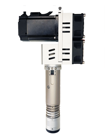
Multi-faceted appearance
Shipping Configuration
perce 91334-A combination blade-standard
perce 91267-A2 combination blade-flagship model
Optional accessories
perce 95284 combination cutter head body
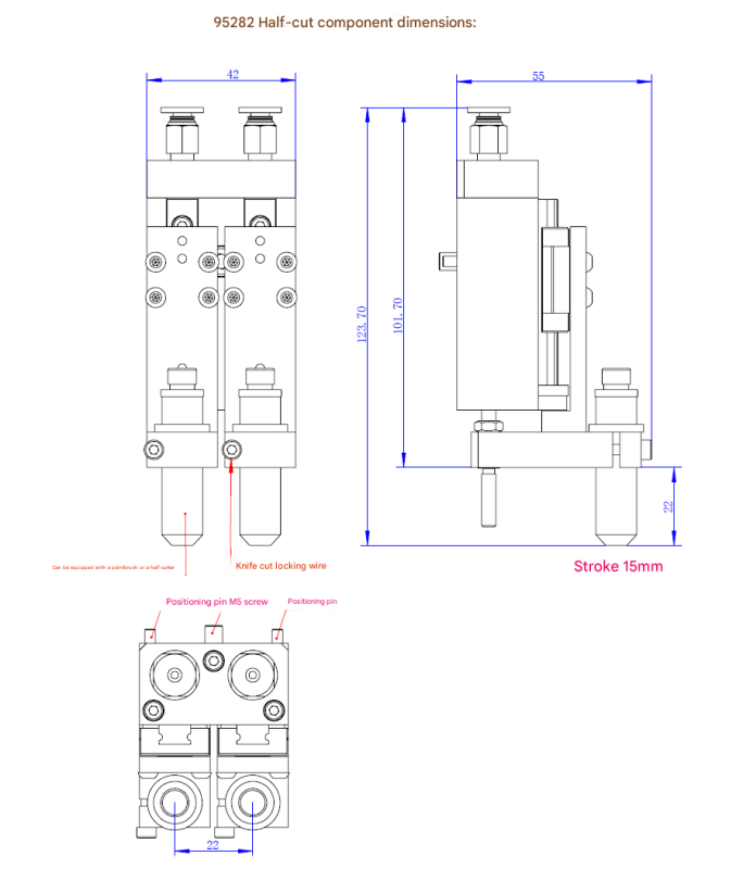
perce 95282 half cut assembly
perce 95283 press cutter assembly
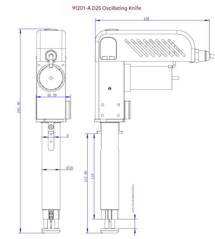
perce 91201-A D25 oscillating knife
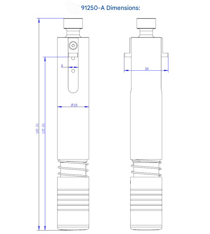
perce 91250 D25 drag knife
perce 91116 small half cutter
perce 95033 half cut blade 2
perce 95019 Half Cut Blade
perce 95170 roller bracket
perce 95061-14 micro wheel 014
perce 95061-15 micro wheel 015
perce 95061-16 micro wheel 016
perce 95294-A small dotted line blade
perce 95287 single bevel assembly
perce 95286 double bevel kit
perce 91246 brush kit
perce 95028 refill
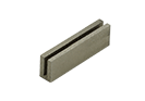
perce 95010 blade clip (0.6311.52mm)
perce 95014 single edge blade (various specifications)
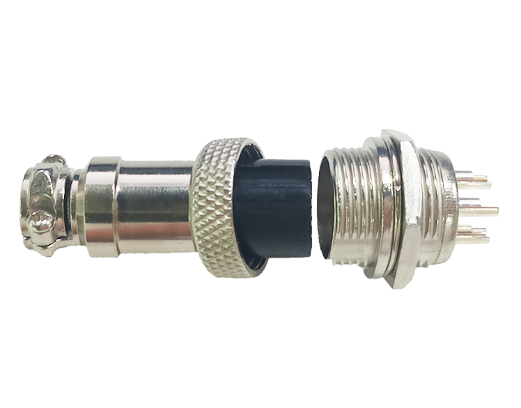
Perce 95136 aviation plug (2, 3, 4, 5 cores)
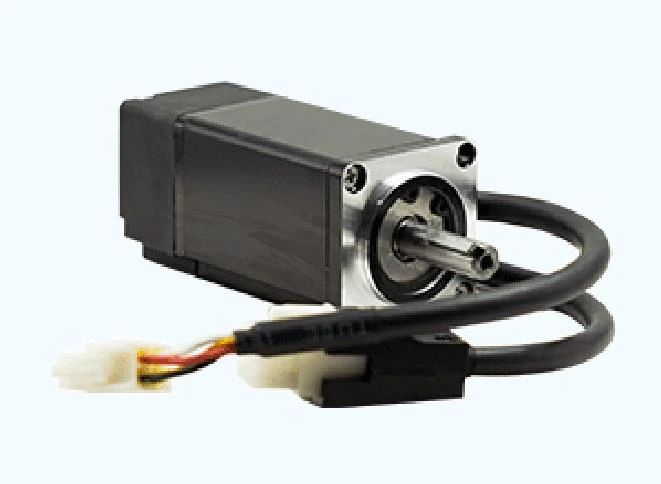
perce 95012 32 motor
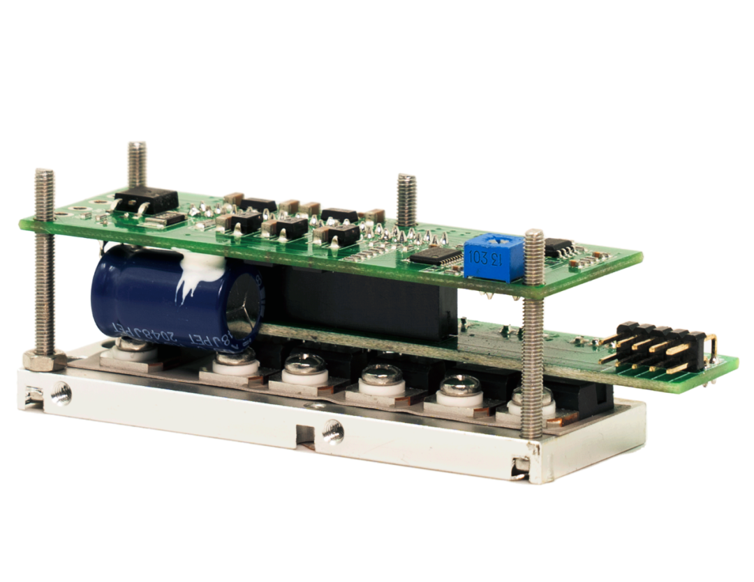
perce 995013 32 driver board
perce 95053 servo motor
perce 95005 coupling
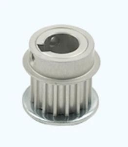
perce 95006 knife seat small synchronous wheel
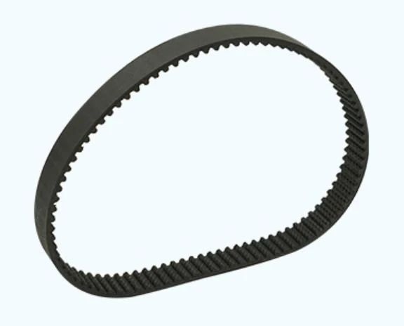
perce 95007 knife holder belt
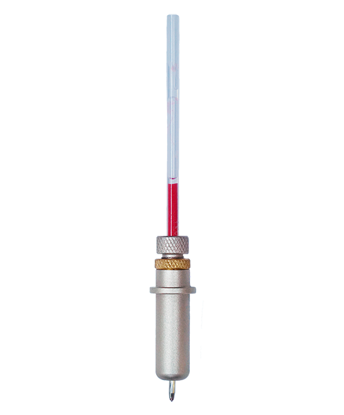
perce 95003 red light indicator
perce 95004 Z-axis limit switch
perce 95008 rotary limit switch
Reviews (0)
Reviews
There are no reviews yet.
Be the first to review “Perce 91267 Combination cutter head(With Electric Oscillating Tool)” Cancel reply
组合刀头带振动刀)-225x300.png)


组合刀头带振动刀)-scaled.png "Perce 91267 Combination cutter head(With vibrating knife)组合刀头(带振动刀)")


Reviews
There are no reviews yet.