Overview
The punching tool holder integrates a knife barrel and a punching module. The knife barrel module can clamp different knife heads such as pneumatic knives, drag knives, and vibrating knives; the punching module clamps the punch and has a punching and cutting function, which can interactively achieve two different process effects of punching and cutting in one clamping. In addition, the punching tool holder is also equipped with a waste collection device, which can collect the waste generated during the processing into the receiving box.
The punching tool holder adopts double guide rails and precision screw drive to realize Z-axis lifting (double guide rails are more stable, shorten the interval to save working area), and adopts synchronous belt drive to realize tool rotation.

Component Description

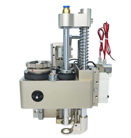
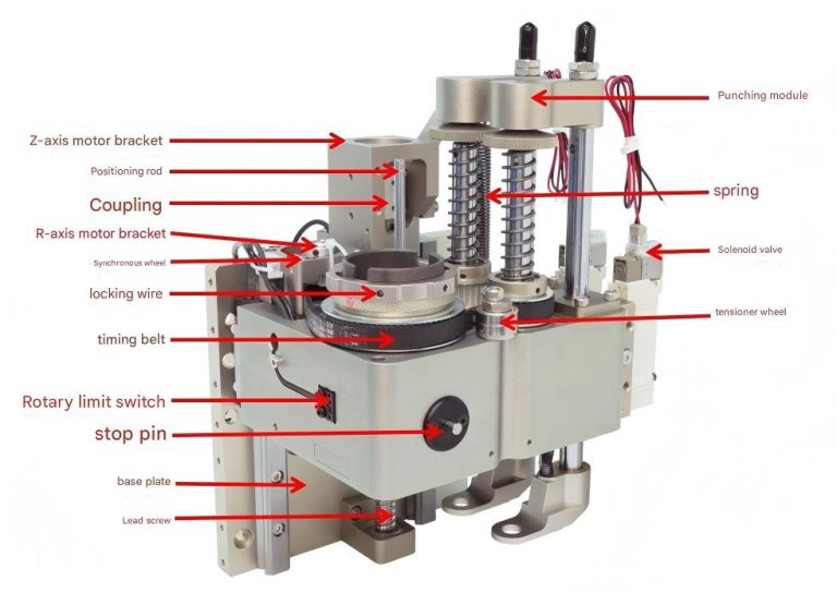
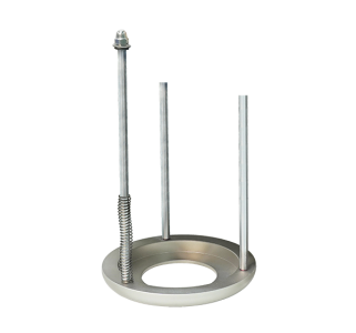
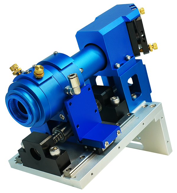
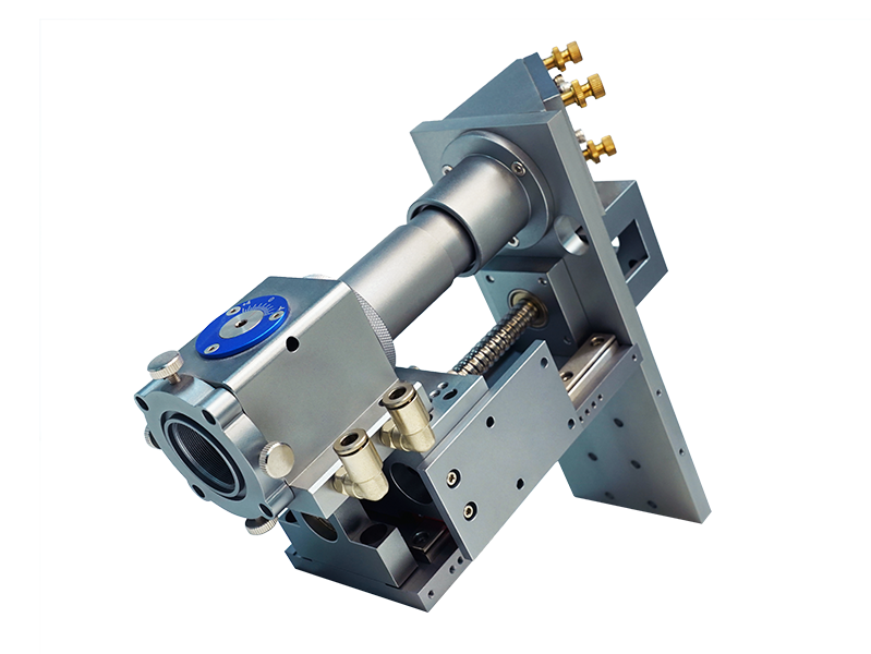
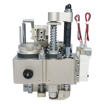
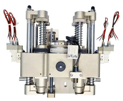
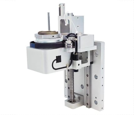
Extension spring:Prevent the tool from sliding down along the Z axis when no power is supplied.
Positioning rod:Used to clamp the tool ears to prevent the upper part of the tool from rotating with the knife barrel.
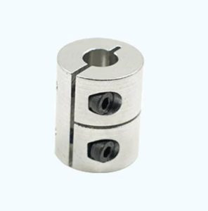
Couplings:Used for connection between Z-axis motor and lead screw.
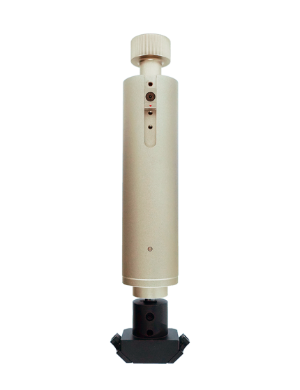
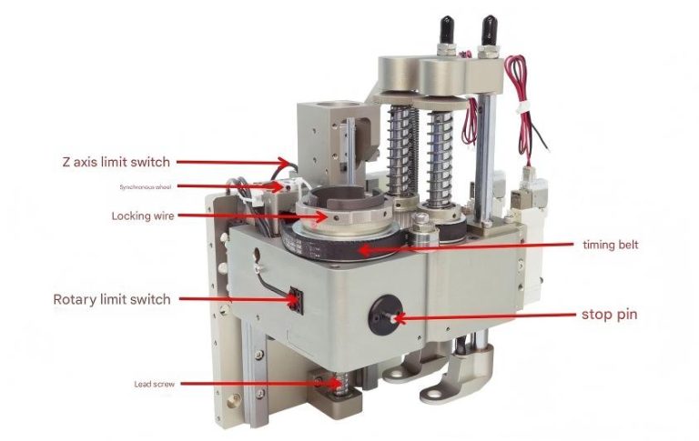
Locking wire:Fixed tool.
Stop pin:When installing the tool and tightening the locking wire, press the stop pin to prevent the knife barrel from rotating.
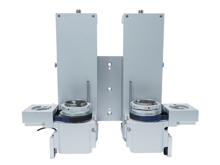
Base Plate:For fixing the knife holder.
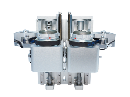
Tensioner:Used to adjust the tension of the synchronous belt.
R-axis motor bracket:Control tool rotation motor installation position.
Z-axis motor bracket:Control tool lifting motor installation position.
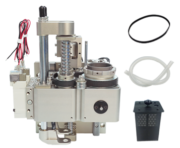
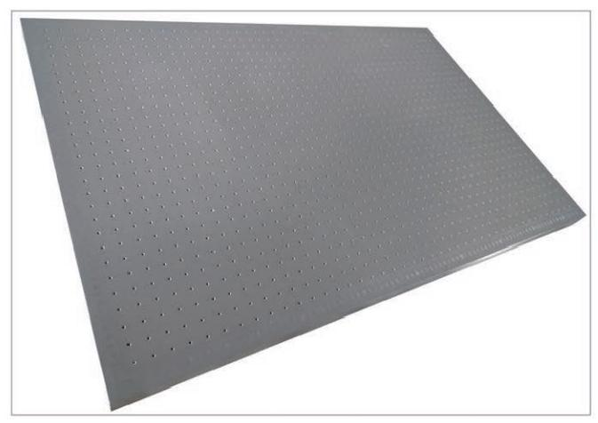
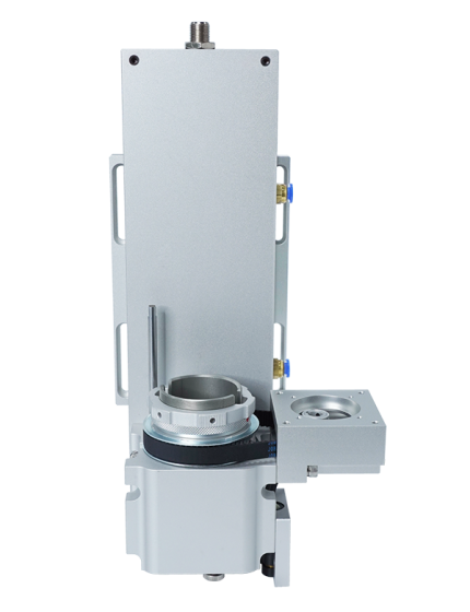
Punching module:Double punching, can be loaded with punches, with punching and cutting function.
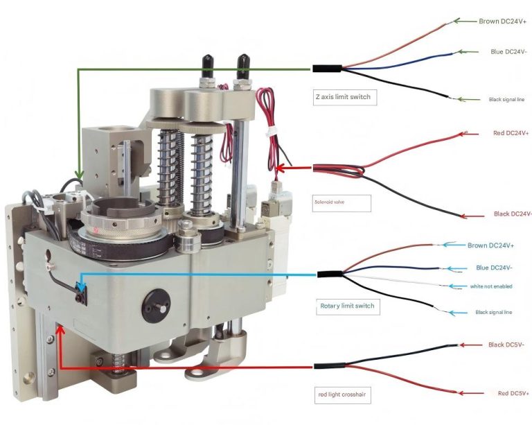
Solenoid valve:Electronic control components, connected to the power system control, gas on and off.
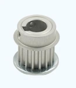
Synchronous wheel:Installed on the R-axis motor.
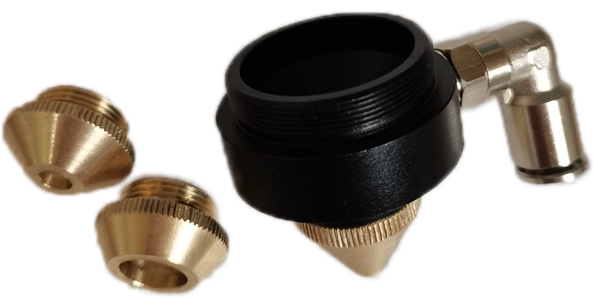
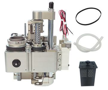
Quick Connectors:Air pipe connector, external compressed gas inlet.
Pipe Fittings:Installed on the negative pressure valve, connected to the external hose, to collect waste chips.
Installation Dimensions


Installation Diagram

Instructions for use and debugging

Lead and gear ratio: lead of screw rod 4mm, gear ratio of synchronous wheel 1:4.
Limit switch output: default output NPN NO.
Stop pin operation: press the stop pin and rotate the knife barrel (synchronous wheel) until the stop pin is inserted into the hole; at this time, the stop pin is stuck in the knife barrel, and the locking wire can be loosened by hand or wrench.
Wiring Instructions

The default power supply for the knife holder red light is DC5V, and the default power supply for the limit switch is DC24V
Red light crosshair | Red: Dc5V+ Black: DC5V- |
Z-axis limit switch | Brown:DC24V+ Blue:DC24V- Black:Signal line |
R-axis limit switch | Brown:DC24V+ Blue:DC24V Signal line see label(black or white) |
Solenoid valve | Red: DC24V+ Black: DC24V- |
Precautions
- Before powering on, make sure the wiring is correct.
- It is required to connect clean and dry compressed gas. (For example, use a pneumatic triplex to filter, reduce pressure and add oil to the gas to ensure the normal operation of the pneumatic actuator and prevent malfunctions due to impurities, excessive air pressure or lack of oil.)
- Use shielded cables to avoid interference.
- Check the tightness of the coupling.
- When the punching module of the punching tool holder is working, the belt rotates clockwise.

Order Model
Product Parameters
Order Model | Perce91326 |
Number of tools that can be installed | 1 |
journey | 87 |
Overall dimensions | W191/H273/D163 |
Weight | 5.8 |
Shipping Configuration

Punch Tool Holder

Punch Tool Holder-left
Optional accessories

Wuxing Press Plate
Optional spare parts

Couplings

Small synchronous wheel of knife seat

Knife holder belt

Rotary limit switch

Z-axis limit switch

Red light indicator
Reviews
There are no reviews yet.